
Sizing conversion options
1", 1/8", 1/16", 1x5mm
Covers the 1 in x 1 in diametrically magnetized cylinder N52 request, 1/8 dia 1/8 thick, 1/16 micro sizes, and 1mm x 5mm diametric magnets.
Run the selector first for a 1mm x 5mm diametric magnet, 1/16, 1/8, or requested 1 in x 1 in N52 sensor check.
Quick sizing tool
The default presets cover standard alias query sizes: a 1 in x 1 in diametrically magnetized cylinder requested as N52, a 1/16 x 1/32 in micro magnet, a 1/8 x 1/8 in diametric magnet, and a 1mm x 5mm diametric magnet. Change the dimensions, gap, grade, and sensor family to get a deterministic first-pass result.
Decimal or fraction input accepted; 0.0625 in equals 1/16 in, and 0.03937 in equals 1 mm.
Decimal or fraction input accepted; 0.03125 in equals 1/32 in, and 0.19685 in equals 5 mm.
Include housing, adhesive, and sensor package stand-off. Large 1 in N52 checks may need a 15 mm or larger screening gap.
Result
Prototype before committing
Estimated field
6.5 mT
The estimate is near the target range; tolerances and mounting stack-up can flip the result. The mT target is a screening baseline for this page, not a universal sensor specification. Confirm the selected sensor threshold, polarity, and temperature drift before committing. Micro/small-cylinder mode ranks early geometry choices; replace it with gaussmeter or sensor fixture data before release.
Metric size
1.59 mm x 0.79 mm
Sensor target
6.0 mT screening baseline
A 1/16 x 1/32 diametric magnet is a micro magnet. It can be useful for compact Hall switching, but the mounting gap and polarity orientation usually matter more than grade alone.
Next step
Prototype on/off detection, index pulses, door or cover state; Check the exact BOP/BRP thresholds and sampling rate in the chosen datasheet.
Sizing conversion options
1", 1/8", 1/16", 1x5mm
Covers the 1 in x 1 in diametrically magnetized cylinder N52 request, 1/8 dia 1/8 thick, 1/16 micro sizes, and 1mm x 5mm diametric magnets.
Tool output
mT estimate
Use the result as a screening value, then validate with the actual sensor threshold.
Field orientation
Side-to-side
Diametric polarity is useful when the sensor reads from the curved side or a rotating target.
Report summary
The tool answers immediate sizing intent; the report below explains the assumptions, limits, and RFQ evidence needed to make the result trustworthy. Updated July 27, 2026.
N42/N52
published evidence split
A requested 1 in by 1 inch N52 cylinder diametrically magnetized should be screened as a high-force, saturation-risk case. Public 1 x 1 diametric catalog examples in the evidence set are N42, while the N52 1 x 1 reference is axial; both point to severe handling and Hall saturation risk, but neither certifies an N52 diametric field map.
90 deg
field axis shift vs axial magnet
The north and south poles sit across the curved diameter, so the usable field changes as the cylinder rotates, creating a clean sinusoidal Bx/By vector pair.
1", 1/8", 1/16", 1x5mm
key design sizes covered
The requested 1 in by 1 inch N52 cylinder diametrically magnetized alias asks for a large-magnet risk screen, while a 1/8" dia 1/8" thick diametric neodymium magnet, the 1/16" size, and the 1mm x 5mm diametric magnet serve compact sensor selection. All belong on this canonical check page.
<2 mm
practical prototype gap target
For sub-2 mm magnets, adhesive layers (0.05-0.15 mm), package stand-off, and housing thickness consume the field margin. In this page model, a 0.5 mm gap change can drop the estimated field by over 50%.
On-Axis
mandatory alignment for 3D Hall
To calculate angle using arctangent (atan2), a 3D Hall sensor must read balanced sine and cosine waves. Diametric cylinders mounted on the rotating shaft axis provide this ideal field.
Pending
public field-at-gap data
Public data verifies unit conversion (1 in = 25.4 mm) and orientation, but exact mT at a 1/8" x 1/8" (e.g. K&J D22-DIA) or 1/16" x 1/32" assembly gap remains pending confirmation until measured in the final fixture.
L/D 5
fragility & alignment challenge
A 1mm diameter by 5mm long diametric rod (L/D ratio of 5) produces a very tight radial field volume. Public N38 catalog data proves the geometry exists, but the magnet must still be kept around 1mm or below from the sensor to prevent signal loss. Its lack of mechanical flats also makes pole alignment difficult without magnetic viewing aids.
The checker converts inch dimensions to millimeters, applies a grade multiplier, penalizes very small magnet volume, estimates open-air field decay with gap, and compares the result with a sensor-family target. Micro magnets use a compact-cylinder screening model; the 1 in x 1 in N52 preset uses a separate large-cylinder saturation risk screen.
The result should not be used as a certified field value. Steel brackets, adjacent magnets, package stand-off, temperature, and magnetizer variation can shift final readings, so prototype measurement remains required.
Screening estimate
Smaller magnet diameters, such as a 1/8 dia 1/8 thick or 1/16 diametric neodymium magnet, result in an accelerated dipole drop-off. The values below are model estimates for N52, not supplier-certified measurements.
| Air Gap (mm) | D101 (1/16" x 1/32" Thk) | D11 (1/16" x 1/16" Thk) | D12 (1/8" x 1/8" Thk) | Sensing Notes |
|---|---|---|---|---|
| 0.5 mm | 160 mT | 280 mT | 460 mT | Very high field strength; risk of sensor saturation on linear models. |
| 1.0 mm (Preset) | 25 mT | 42 mT | 65 mT | Optimal air gap for micro sensors; robust signal margin. |
| 1.5 mm | 5.2 mT | 9.8 mT | 16.5 mT | Digital switches can trigger; Linear sensors struggle with resolution. |
| 2.0 mm | 1.2 mT | 2.6 mT | 4.8 mT | Undersized for reed switches; requires high-sensitivity Hall sensors. |
| 2.5 mm | 0.4 mT | 0.9 mT | 1.8 mT | Approaching sensor noise floor; only magnetometer can resolve. |
| 3.0 mm | <0.2 mT | 0.3 mT | 0.7 mT | Failed state for micro sizes. High risk of mechanical vibration fault. |
Decision boundary: use this table to rank candidate sizes and gaps. Do not use it as a drawing acceptance value; final mT must be measured with the chosen sensor, housing, adhesive stack, magnet coating, and production lot.
Mechanical tolerance design
For rotational encoder systems, radial misalignment distorts the sine/cosine flux vectors, causing significant angular calculation errors.
| Radial Offset | Angle Error | Field Loss | System Consequence |
|---|---|---|---|
| 0.1 mm | 0.2° to 0.4° | <2% | Negligible impact. Well within 3D Hall (e.g. TMAG5170) calibration capability. |
| 0.2 mm | 0.8° to 1.5° | 5% to 8% | Arctangent (By/Bx) amplitude skew. Measurable accuracy degradation; requires look-up table correction. |
| 0.3 mm | 2.0° to 3.5° | 12% to 18% | High angle error. Saturation or noise floor problems at phase transitions during rotation. |
| 0.5 mm | 5.0° to 9.0° | 25% to 40% | Critical assembly failure. Differential readings fail; signal distorted beyond simple linear correction. |
The offset values are planning estimates for compact end-of-shaft angle layouts. Treat them as a tolerance budget starting point and replace them with calibration data from the actual 3D Hall or angle sensor.
Environmental survivability
NdFeB magnets exhibit negative temperature coefficients. Standard grades demagnetize permanently at 80°C; high-temp variants are required for industrial environments. Confirm the exact operating temperature rating against the supplier's grade datasheet.
| Magnet Grade | Max Temp Limit | Curie Point | Temp Coef (Br) | Stability Behavior |
|---|---|---|---|---|
| N52 (Standard NdFeB) | 80°C (176°F) | 310°C | Br: -0.12%/°C, Hcj: -0.75%/°C | Reversible Br loss up to 80°C. Exceeding it causes permanent demagnetization; Hcj drops fast rendering it susceptible to external field knocks. |
| N42H (High Temp NdFeB) | 120°C (248°F) | 340°C | Br: -0.11%/°C, Hcj: -0.58%/°C | Standard choice for brushless motor rotary sensors. Higher intrinsic coercivity (Hcj >= 1353 kA/m) protects against thermal knockdown. |
| N38SH (Super High Temp) | 150°C (302°F) | 350°C | Br: -0.10%/°C, Hcj: -0.52%/°C | Best choice for automotive under-hood sensors and heavy machinery with stable loops up to 150°C (Hcj >= 1592 kA/m). |
| N35UH (Ultra High Temp) | 180°C (356°F) | 350°C | Br: -0.09%/°C, Hcj: -0.49%/°C | Sourced for aerospace actuators and downhole tools. Retains coercivity (Hcj >= 1990 kA/m) against external reverse demagnetizing fields. |
| SmCo 26 (Samarium Cobalt) | 300°C (572°F) | 750°C | Br: -0.035%/°C, Hcj: -0.20%/°C | Exceptional thermal stability (3-4x more stable than N52). Lower initial field (Br ~ 1.05 T) but vastly outperforms NdFeB above 150°C. |
Temperature classes differ by supplier and magnet geometry. The table is suitable for RFQ scoping, but production release still needs supplier grade data, coating compatibility, and a hot/cold sensor-output test.
Geometric design principles
Depending on the application, choose the sensor orientation (axial face vs. side-shaft) to match the sinusoidal change in magnetic vectors.
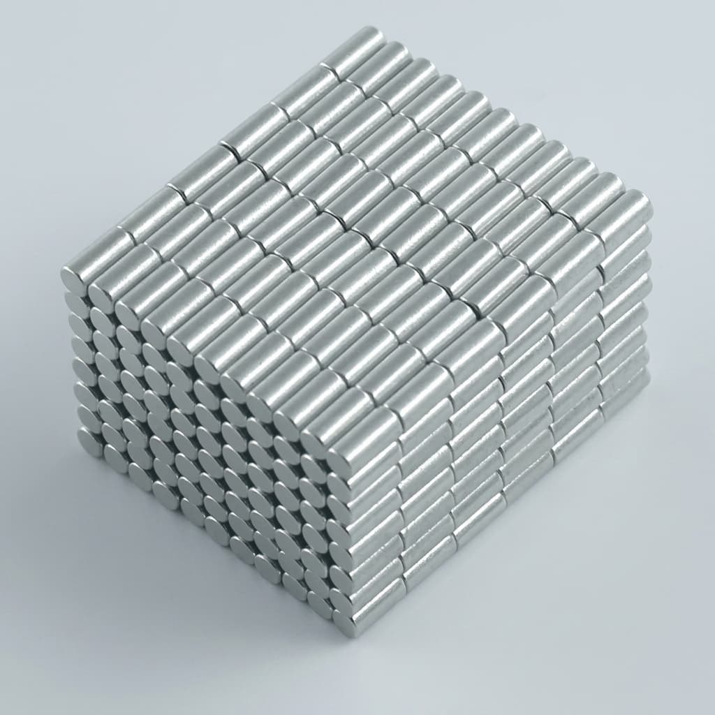
Product reference
The selector is a screening tool. For a 1mm x 5mm diametric magnet, requested 1 in by 1 inch N52 cylinder diametrically magnetized, 1/8 dia 1/8 thick diametric neodymium magnet, or compact 1/16 x 1/32 in sensor target, final approval still depends on the actual magnet lot, sensor threshold, housing wall, adhesive thickness, nearby steel, and temperature profile.
Alias size decision check
The exact conversion is fixed; the magnetic field at the sensor is not. Treat this size as a prototype starting point unless a supplier provides fixture-specific measured data.
| Decision question | Evidence-based answer | Action |
|---|---|---|
| What does the requested 1 in by 1 inch N52 cylinder diametrically magnet alias need? | It needs a large-magnet saturation and handling-risk decision, not another thin product page. Public evidence supports the 1 x 1 diametric geometry through N42 examples and comparable 1 x 1 N52 strength through an axial catalog item, so the N52 preset is a risk screen rather than proof of a stocked N52 diametric line. | Run the large-N52 preset, require supplier confirmation of N52 diametric magnetization, protect the assembly from pinch hazards, and measure Bx/By across tolerance before RFQ release. |
| Are the 1/8" x 1/8" and 1/16" x 1/32" sizes credible? | Yes. The 1/8 dia 1/8 thick diametric neodymium magnet is highly credible under 2 mm air gaps; the 1/16" size is limited to short-gap cues and compact fixtures under 1 mm. | Keep the first prototype gap near 1.0-1.5 mm for 1/8" sizes. |
| How should a 1mm x 5mm diametric magnet be evaluated? | The 1mm x 5mm size (L/D = 5) provides an extended axial sensing zone but a very limited radial field. Because it is only 1mm in diameter, it is prone to snapping during handling and requires a sensor gap around 1mm or below. | Pre-assemble it into a protective micro-tube or sleeve, and use magnetic viewing film to ensure the diametric poles face the sensor. |
| Can N52 compensate for loose mechanics? | Only partly. Grade changes are smaller than the field loss caused by increasing gap on these sub-4 mm magnets. | Reduce stand-off, increase magnet volume, or change the sensing geometry before relying on grade alone. |
| What public claim should be avoided? | Avoid claiming a guaranteed mT value at a specific gap for these micro/small sizes unless the supplier provides measured data for the same fixture. | Mark field-at-gap values as pending confirmation until fixture data exists. |
| Evidence source | Time marker | How to use it | Known boundary |
|---|---|---|---|
| Texas Instruments TMAG5170 datasheet | Specs verified July 20, 2026 | Defines selectable magnetic field ranges for 3D Hall angle sensing. TMAG5170A2 supports ±75, ±150, and ±300 mT ranges, so fields above the selected range can clip angle calculations. | The page uses ±300 mT as a practical upper guardrail, but the exact limit depends on the selected sensor orderable and range code. |
| JBF National neodymium cylinder catalog | Verified July 20, 2026 | Confirms a public 1 in x 1 in diametrically magnetized cylinder catalog line, matching the alias geometry and direction language. | The cited catalog line is N42, so it proves geometry and direction wording only. If the RFQ requires N52, verify grade, magnetization direction, and lot field data with the supplier. |
| Applied Magnets 1 in x 1 in Diametrically Magnetized Cylinder Catalog | Verified July 20, 2026 | Documents a public 1 in x 1 in diametrically magnetized cylinder example with N42-class published BrMax and 90 lb pull-force context. The page uses it for geometry, orientation, and handling-risk evidence for the alias. | It does not prove an N52 diametric catalog item or fixture mT value. The exact magnetic flux at a sensor gap must still be determined in the final assembly. |
| totalElement 1 x 1 in N52 cylinder catalog | Verified July 20, 2026 | Lists a comparable 25.4 x 25.4 mm N52 cylinder with 6,350 Gauss surface field and 75.5 lb pull force, supporting the saturation and handling-risk screen. | This reference is axially magnetized, so the page uses it only as comparable catalog surface-field and safety evidence. The final diametric side-field map must be measured in the fixture. |
| NIST SI unit guidance | Current public guidance checked June 24, 2026 | Use the exact inch relationship for conversion: 1 in = 25.4 mm, so 1/16 in = 1.5875 mm and 1/32 in = 0.79375 mm. | This proves size conversion only; it does not predict magnetic flux density. |
| TI TIDA-060040 3D Hall angle reference design | Reference design TIDA-060040 checked June 24, 2026 | Supports 3D Hall angle-measurement geometry, magnet placement vocabulary, and the need to validate sine/cosine signal balance in the final mechanical stack. | The public design material does not certify a universal 1/16 in diametric magnet field value; concentricity and gap still require fixture measurement. |
| Diametric magnet supplier drawings (e.g. K&J) | Catalog convention checked June 24, 2026 | Confirm that diametric magnetization places north and south poles across the cylinder diameter rather than on the flat faces. | Supplier drawings are useful for polarity orientation, but open catalog pages rarely certify mT at the buyer assembly gap. |
| Prototype gaussmeter or sensor fixture | Required before drawing release | Measure the final assembled gap, polarity, and signal repeatability across tolerance and temperature extremes. | Open-air estimates miss steel, shielding, PCB copper, tolerance, adhesive thickness, and adjacent magnets. |
| Page screening model | Internal estimator reviewed June 24, 2026 | Use the listed mT, thermal, and offset figures as early screening estimates to compare design directions before samples exist. | These figures are not supplier-certified measurements and must be replaced by measured lot data before production release. |
| UMAGNETS 1mm x 5mm N38 diametric neodymium rod catalog | Verified July 27, 2026 | Validates a public 1mm diameter x 5mm length diametrically magnetized neodymium rod example in N38 grade for compact sensor triggers. | Due to the 1mm cross-section, NdFeB is extremely brittle. The catalog proves availability and wording, not a guaranteed mT value in the buyer fixture. |
Source note: public supplier catalogs and device datasheets are appropriate for geometry, magnetization direction, and sensor threshold definitions. They are not enough to prove final field strength for a requested 1 in by 1 inch N52 cylinder diametrically magnetized, a 1/8 dia 1/8 thick, or a 1/16 x 1/32 diametric magnet inside a real assembly; that remains pending confirmation until the actual sensor, gap, housing, and magnet lot are measured together.
Send measured-gap RFQThe checker uses repeatable baselines so the page can compare options, but procurement should replace these with the exact datasheet limits for the chosen part. For example, TI Hall switch literature distinguishes BOP, BRP, and hysteresis; reed switch resources specify sensitivity in ampere-turns; AKM magnetometer families publish measurement range by axis and mode.
| Sensor family | Real decision input | Tool baseline | Limitation to test |
|---|---|---|---|
| Digital Hall switch | Operate/release point, hysteresis, sample rate | 6 mT | A low-power switch can miss a short pulse if sampling rate and magnet speed are not checked. |
| Linear Hall sensor | Linear range, sensitivity, saturation limit | 12 mT | A stronger magnet can hurt accuracy if it pushes the output near saturation. |
| Reed switch | Operate ampere-turns, release ampere-turns, orientation | 10 mT | Reed behavior is geometry-sensitive; test pull-in/drop-out with the real magnet path. |
| Magnetometer / compass IC | Measurement range, offset calibration, hard/soft iron error | 1.5 mT | Nearby steel and permanent magnets can dominate the intended micro-magnet signal. |
Side-mounted digital Hall switches, very compact index points, low-inertia rotating targets, and assemblies where the magnet can be keyed.
Linear Hall position checks, reed switches, and magnetometers where calibration or gap control is available.
Large air gaps, unknown polarity orientation, high-temperature zones without grade validation, or safety-critical sensing without measurement data.
| Option | Best for | Tradeoff |
|---|---|---|
| Diametric cylinder magnet | Rotary index, side-mounted Hall sensing, compact angle cues | Orientation must be controlled during assembly |
| Axial cylinder magnet | End-on proximity, reed switch actuation, simple fixturing | Less useful when the sensor reads from the cylinder side |
| Ring magnet, diametric | Shaft-through rotary sensing and encoder targets | Higher cost and tighter concentricity requirements |
| Magnet pair or molded target | Higher field margin or custom pole pattern | More parts, tooling, and validation work |
Control three failure modes: wrong polarity orientation, undersized field margin, sensor saturation or pinch hazards on large N52 cylinders, and supplier substitution without a drawing note. Mitigate them with guarded/keyed fixtures, measured sensor output at tolerance extremes, and an RFQ that explicitly says diametrically magnetized, not axially magnetized.
Sources checked July 27, 2026. These references support conversion, threshold vocabulary, supplier geometry, and sensor-family boundaries. They do not replace a measured field map for the exact 1mm x 5mm, 1 in N52, 1/8, or 1/16 magnet assembly.
Used for 3D Hall magnetic field range limits, including the ±300 mT A2 guardrail checked July 20, 2026.
Used to verify public supplier language for a 1 in x 1 in diametrically magnetized cylinder geometry; cited grade differs, so N52 must be confirmed in RFQ.
Used for a public 1 in x 1 in diametrically magnetized cylinder example and handling-risk context; cited data is not treated as certified N52 diametric fixture data.
Used for comparable 1 in x 1 in N52 surface-field and pull-force risk context; final diametric side-field still requires measurement.
Used to verify public supplier wording for a 1mm x 5mm diametrically magnetized neodymium rod and to keep the tool preset conservative at N38.
Used for exact inch-to-millimeter conversion context.
Used for 3D Hall angle-measurement geometry, magnet placement context, and final fixture-validation framing (verified June 24, 2026).
Used for BOP/BRP, hysteresis, sampling, and temperature threshold terminology.
Used for reed operate/release and ampere-turn sensitivity framing.
Used for magnetometer range and calibration boundary framing.
Premise
Requested 1 in by 1 inch N52 cylinder diametrically magnetized, TMAG5170 sensor
Process
Due to comparable catalog surface-field values around 635 mT, the sensor should start with a large >15 mm screening air gap. Mechanics must handle severe pinch hazards during assembly.
Result
Provides a strong signal through thick fluid or safety housings, but requires rigid mounting to prevent the extreme magnetic force from ripping the fixture apart.
Premise
1/16 x 1/32 in diametric N52 magnet, 1 mm nominal gap
Process
Use the tool preset, keep the sensor on the curved side, and test operate/release through the plastic wall.
Result
Likely workable only if assembly tolerance stays tight and polarity is keyed.
Premise
1/16 x 1/8 in NdFeB magnet, 120°C ambient, 1.5 mm gap
Process
Evaluate N42H grade to prevent thermal demagnetization, calculate field loss at 120°C (-12%).
Result
Standard N52 fails reversibility; upgrading to N42H ensures stable 8.6 mT signal at gap.
Premise
1/16 x 1/16 in diametric magnet, 3D linear Hall (TMAG5170)
Process
Align magnet end-of-shaft with 0.1 mm concentricity control, sample sine/cosine signals.
Result
Achieves <1° rotational accuracy. Key validation is shaft eccentricity tolerance.
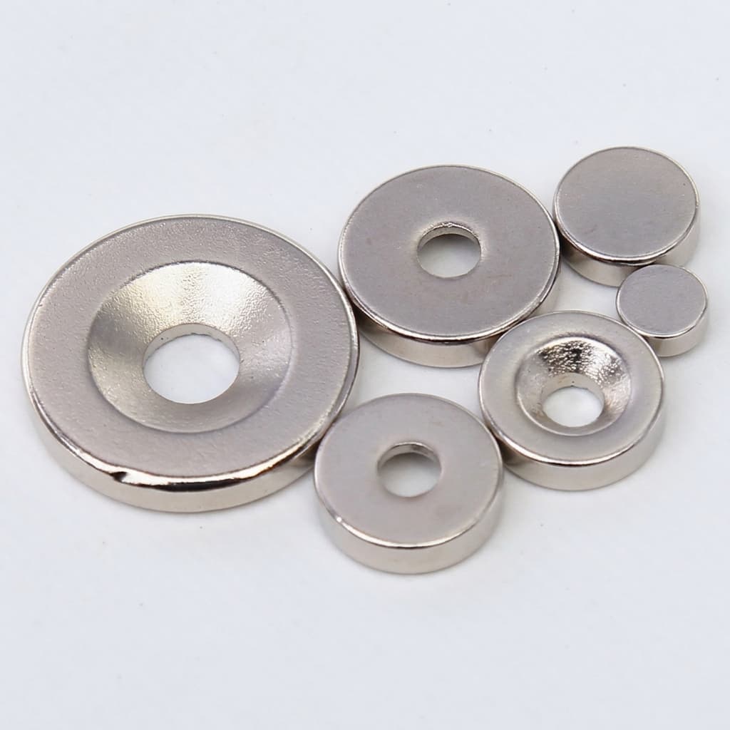
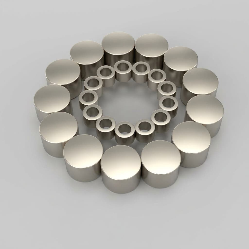
These images are selected from the current product image set by diametric and encoder-related filenames. Use them to clarify RFQ intent when describing micro cylinders, disc stacks, or ring-style sensing targets.
Engineering QA
Comparable 1" diameter by 1" thick N52 axial cylinder catalog data lists about 6,350 Gauss (635 mT) surface field, while public 1" x 1" diametric variants in the evidence set are N42 and list BrMax plus pull-force context. Treat a requested N52 diametric version as a high-field RFQ risk until the supplier confirms grade, magnetization direction, and fixture field data.
Yes. Both the 1/8 dia 1/8 thick diametric neodymium magnets and 1/16 diametric magnets represent specific sizing queries inside the diametric magnet intent cluster. This canonical page covers all small diametric cylinder parameters to prevent duplicate pages.
For 1/8 x 1/8 in, it converts to exactly 3.175 x 3.175 mm under standard NIST conversion factors (1 inch = 25.4 mm). For 1/16 x 1/32 in, it converts to 1.5875 x 0.79375 mm. These are standard catalog references for sensor actuators.
A 1mm x 5mm diametric magnet is a high-aspect-ratio micro cylinder commonly used in compact rotary encoders, side-mounted digital Hall switches, or medical devices where radial space is extremely limited but a stable sine/cosine magnetic flux vector is required.
The search intent and design path for a 1/8 dia 1/8 thick diametric magnet is not separate from the general diametric magnet selection. Sourcing, air gap calculations, and sensor-matching rules are identical, so merging them avoids thin duplicate content.
Br (e.g., 14,800 Gauss or 1.48 T for N52) is a material property representing closed-circuit magnetism. Surface gauss is the actual open-air density measured at the magnet surface (usually 2,500-3,500 Gauss for micro magnets), which decays rapidly with distance.
Very small magnets act as magnetic point dipoles much closer to their surfaces. This means their field strength decays by the inverse cube of the distance (1/z³) almost immediately, whereas larger magnets decay slower in the near field.
For small diametric magnets, the magnetic dipole model (Bx, By proportional to 1/z³) is only valid when the distance z is at least 3 times the magnet diameter (z > 9 mm for 1/8" magnets). At sub-2 mm gaps, one must use charge models or finite element analysis (FEA) because near-field boundary effects dominate.
Yes, but only with a controlled air gap, supplier-confirmed diametric N52 data, and a measured field map. A TMAG5170A2-class 3D Hall angle sensor uses ranges up to ±300 mT, while comparable 1"x1" N52 axial catalog surface field is already around 635 mT. Start with a large spacing, typically around >15 mm, or choose a smaller/weaker magnet if the package cannot provide that clearance.
Side-mounted Hall sensors and 3D angle sensors (like TMAG5170) are the most common fit. Reed switches can work, but their spatial lobes make orientation highly sensitive.
No. Upgrading from N35 to N52 increases field strength by about 30%, but increasing the air gap by just 0.5 mm can reduce field strength by 50% or more. Mechanical gap control is primary.
No. The calculator is an analytical estimator for quick screening. Highly critical sensor designs should use finite element analysis (FEA) or real-world gaussmeter fixtures.
Standard digital Hall switches trigger between 3 mT and 10 mT. Highly sensitive ones can trigger at 1.5 mT, while low-sensitivity industrial switches might require 20 mT.
A rotating diametric magnet produces sinusoidal flux components (Bx, By) relative to the sensor. High-resolution encoders calculate the arctangent of these signals to determine angle.
Using a 1/8" x 1/8" (D22-DIA) N52 magnet at 1.0 mm gap yields ~65 mT, giving excellent margin for a 10 mT industrial switch. However, at 2.0 mm, the field drops to 4.8 mT, requiring a high-sensitivity sensor (Bop <= 3.0 mT). This leaves the system vulnerable to external EMF noise, making gap enforcement critical.
Polarity orientation and eccentricity offset. A diametric magnet must be keyed or aligned so the poles rotate correctly relative to the sensor axis, and offset must be minimized.
Yes, especially with side or center-reading magnetic angle sensors. Accuracy depends on concentricity, air gap, field strength, and calibration.
Concentricity errors skew the sine/cosine signal balance, leading to angle errors. A 0.2 mm radial offset can cause up to 1.5 degrees of encoder angular error.
Adhesive layers (usually 0.05 to 0.15 mm) add directly to the physical air gap. For a 1/16" micro magnet, this represents a significant fraction of the usable field distance.
For a short cylinder (1/8" or 3.175 mm length), axial shift moves the sensor into the magnet's fringe fields where magnetic vectors bend sharply. This causes severe sine/cosine amplitude mismatch, leading to angular errors. Secure axial locking via steps or rings is vital.
Because it is a smooth 1mm cylinder, there are no mechanical flats to indicate where the North and South poles sit on the curved sides. You must use a reference magnet, a gaussmeter, or a magnetic viewing film to find the poles, and then physically mark or immediately pot the magnet in its fixture to lock the orientation before it rotates.
Send diameter, thickness, material grade, coating, magnetization direction (diametric), tolerance, operating temperature, sensor part number, nominal gap, and annual volume.
Exact field at a given gap for a 1/16 x 1/32 magnet varies by material, coating, magnetizer, and fixture. Public catalog pages rarely prove final assembly performance.
Build one fixture at the intended gap, verify polarity, record sensor output across tolerance extremes, then freeze the magnet drawing.
Choose axial when the sensor reads the magnet from the flat face or when simple end-on proximity switching is the main requirement.
Explicitly specify "DIAMETRICALLY MAGNETIZED" in bold on the engineering drawing and RFQ, and demand a sample run verification report.
Yes. Place a known axially magnetized magnet near the curved side of the cylinder. If it is axially magnetized, it will attract only at the flat circular faces. If it is diametrically magnetized, it will self-align and snap to the sides along its N-S pole boundaries. Using a magnetic flux viewing film will also reveal a clear diametrical dividing line.
Related engineering paths
These internal paths keep the 1 in by 1 inch N52 cylinder diametrically magnetized alias inside the canonical diametric cluster while giving buyers practical next steps.
Keep all size variants, including the 1 in by 1 inch N52 cylinder diametrically magnetized, the 1/16 diametric magnet (such as 1 16 x 1 32 diametric magnet), 1/8 dia 1/8 thick diametric neodymium magnets, and the 1mm x 5mm diametric magnet on this canonical URL. For sourcing, send the target sensor part, nominal gap, operating temperature, drawing, and required annual volume so the quote can be checked against the real sensing boundary.
Inquiry Email
Include drawing, dimensions, material, coating, magnetization, quantity, and delivery location.
Instant Chat
+86 18857971991
Direct channel for RFQ details and engineering clarification.
The alias anchors 1 in x 1 in diametrically magnetized cylinder, 1 16 diametric magnet, 1/8" dia 1/8" thick diametric neodymium magnet and 1mm x 5mm diametric magnet resolve to this same canonical page. No dedicated alias routes are published.